Part 2: Assembly
First things first: If you are able to pull the engine out, do it. You will spend a lot more extra time doing this with the engine in the car since everything is such a tight fit.
I had pulled the engine for round 1, but this time around I did everything with the engine in the car. It isn't as bad as others make it seem but I still recommend pulling the engine if you have the ability to do so. With the engine out, it is a perfect time to regasket everything. You can get rid of the entire CCV system. If the car is an automatic, the stock E46 transmission cannot take the torque. Either do a manual swap or 8HP swap. If sticking to manual, I recommend a clutch kit from Hopwood Motorsports. I run the single disc in my clutch and it feels completely like stock, although I recommend going with the twin disc so you don't have to change out the clutch for a second time when you go for more power.
You will have to remove a lot of the plastic ducting to make clearance for the intercooler and piping. It may be possible to work around them but unfortunately the plastics on my car were all broken so I didn't have a clean slate to start with. You will most likely have to remove the brake ducts, lower portion of the fender liners, the plastic undertray, the aluminum under brace (although it's possible to work around this one), and the shroud in front of the radiator directly behind the bumper.
If your car was originally automatic or doesn't have the electric fan in the engine bay but rather directly behind the bumper, you will need to convert to the manual style fan which gets rid of the clutch fan and moves the electric fan to inside the engine bay. This is done to give clearance for the intercooler.
The first modification you will be doing is for the fuel tank purge valve. The piece that clips on the bottom will be left alone but the hose on the rear end going into the intake manifold will be plugged up (circled in blue) on the intake manifold side and you will let the end on the purge valve breathe out into free air. When I first did this, I had only blocked the hose near the valve as opposed to the piece itself that is under the intake manifold. Little did I know that it had popped off from boost. With the manifold off, just clamp a vacuum cap over it.

There are two locating tabs (cicled in black) intended to align the stock intake boot. Those two tabs do not allow you to slide on the silicone coupler all the way on so you have to grind them down.

There will be an ear on the transmission that you will have to grind down as it interferes with the downpipe. If you look close at the picture, you can see the dust left over from where it was ground down. I don't have a close up pic when I had it done but it should look something like this.

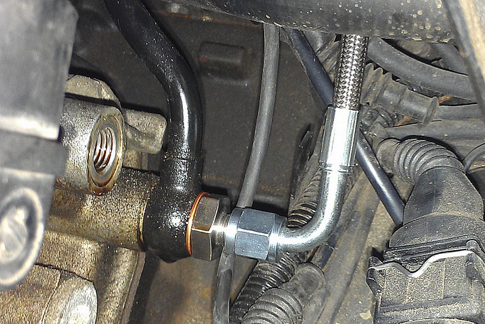
This manifold places the wastegate in an odd location. You need to make a custom relocation pipe. You will utilize 1.5" piping. For your wastegate reference, do not get it from the intake manifold! The
wastegate diaphragm isn't supposed to see vacuum. If your turbo compressor housing has the fitting on it, use it. If it doesn't, get a bung welded onto your intercooler piping and reference it off of that or tap the raised section on your compressor housing where the fitting was intended to go. I ended up using Walker 41231 which is a piece of mandrel bent 1.5" 90 degree pipe. However, I did also has a short 90 welded onto the flange that bolts to the manifold so I recommend ordering 2 pieces of the pipe. I opted to dump my wastegate to atmosphere as it made things simpler. In order to recirculate the wastegate, from what I've seen, it needs to be placed considerably further back which can influence boost creep.


If the banjo bolt for your wastegate is too close to the turbine housing, you can clock your wastegate. Here's how mine is

Here is what my downpipe looks like. It appears the redesigned SPA manifold (2019+) places the turbo in a better location which allows you to clear the chassis without having to use pie cuts which is really nice and makes things much easier. I am using the older style which is why mine isn't as smooth.


As for the rest of the exhaust system, I had that piece done at an exhaust shop. It is one 90 degree mandrel bend cut in half and flipped then welded back. The majority of the exhaust is straight. I have a valved system at the end where the stock muffler went to switch between fully straight piped and muffled. You can check it out here

Behind the intake manifold, there are three nipples which usually have torn caps on them. You will utilize one, two, or all three of these depending on your setup. One will have a line for your BOV reference (if you want to use one; I didn't), the other will have a line for your boost gauge running into the cabin, and finally, one will run to your fuel pressure regulator if your tuner prefers it. If you are going to run the line for your fuel pressure regulator to one of the nipples, you no longer need to use the F connector piece and can just run the sucking jet pump hose straight to the 3/8" barb on your charge pipe. Replace the cap on the unused one(s) with a BMW piece ordered from the parts list. Use hose clamps to secure those in place. You can remove the check valve (black and white piece) and solenoid that is clipped on near the nipples that was used for the SAP (if you kept the DISA, which you should, read here).

After you have removed your stock exhaust manifolds, you will have to
use the double nut method to remove any left over studs and install your N54/N47 studs. It is going to be difficult to fully tighten the nuts, but it is doable. Don't be afraid to cut up a wrench to give you clearance. I used a combination of small wrenches, wobble head wrenches, and wobble sockets to get my nuts tightened.
When I did my first setup, the nuts had loosened from heat cycling. Normally, this wouldn't happen because BMW also uses clad nuts. However, because the N54 studs do not give you many threads to work with, you may have to go in and retighten all the nuts after a couple heat cycles.
When you are going to install the turbo to the manifold, use red Resbond on the studs that are to be installed into the manifold and on the nuts that will be securing the turbo to the manifold. Do not forget to tighten these because it is VERY difficult to access the nuts once the engine is back in the car. To be able to install all 4 nuts that hold the turbo to the manifold, you unbolt the CHRA from the turbine housing and it gives you plenty of access to tighten all 4 nuts. After you get all 4 nuts on, you have to reinstall the CHRA which is a bit challenging to do given the limited amount of space you have to work in but I did it twice with the engine in the car and it is fully doable. As with installing the manifold, don't be afraid to cut up some wrenches to make custom tools to tighten up the bolts for the compressor housing to CHRA.
You will need to hammer right under the passenger footwell in order to get clearance for your downpipe. If your exhaust touches the body anywhere, it transmits the vibrations throughout the entire car and it is very unpleasant. If you think you've hammered enough, think again. Really beat the crap out of that area. As I had mentioned earlier, it appears the new manifold do not have this issue with clearance for the downpipe.

The oil feed line gets really close to the manifold so I wrapped it in exhaust wrap. I also used a 90 degree adapter and hose clamped the feed line to my AC line
to keep it away from the manifold. Ideally you want to use p-clamps to prevent damaging the feed line from movement.

One end of feed line threads into the rallyroad banjo adapter behind oil filter housing where the VANOS line is. I ran my line over the top of the valve cover, however to keep things clean, you can route it along the front of the engine tucked behind the thermostat.
I ended up using oval piping to give me some ground clearance. I tried one method of running the piping fully over the subframe but it required a really tight angle to go from the turbo to the rest of the piping. You could make this work if you cut the turbo's outlet and weld a short cast 90 angle to it. I couldn't work out a proper angle with couplers so I just scratched that idea. You are able to squish a 2" coupler and clamp to fit the pipe perfectly. I have attached a picture of the dimensions in case it can't be found in the future. I ran a zip-tie through the clamp and around the sway bar to help keep the charge pipe higher off the ground.


 >
>


I will admit, I am not a fan of how I have the piping routed. There are too many bends and couplers which is a recipe for boost leaks. If you have the ability to weld or have easy access to a fabricator, I highly recommend going with what I mentioned earlier to keep life simple. Now, the way I have it now works and I don't scrape, even with my car being lowered. However, a major downside with running through the sway bar as opposed to around is you need to make sure it's angled right or else once the car is lowered onto the ground, the coupler gets squished. With the car in the air, it looks like you have miles of clearance. I learned that the hard way. The reason I went through and not around the sway bar is so I can fit a full 4" intake.
Cold side is pretty much the same regardless of manifold used.
2x 3" 90 degree coupler (one coupler will have long legs 4.7" and the other will be regular length)
1x 600mm 3" 45 degree aluminum pipe
1x 3" straight coupler (2.5" to 3" if your intercooler outlet is 2.5")
1x 3" 90 degree aluminum pipe (make sure it has a long straight section before the bend)
You would shorten one of the straight legs of your 90 degree pipe and connect it to your intercooler outlet (it may need shortening on both ends). The other end gets a 90 degree coupler slid onto it which should now bring the outlet near the expansion tank. Turn the coupler to face the back of the car and if the leg is the right length, you should be able to slide the 45 degree pipe coming off the throttle body right into that 90 degree coupler.
If you are going to be running a MAF, you want to make sure there is long piece of straight pipe in front of it to prevent turbulence and causing funky MAF readings. Also, you must leave a good amount of space between the MAF and ICV or else the ICV will throw off the MAF reading. Your ICV and f-connector will attach to the charge pipe to retain stock functionality. Refer to here on how to boost proof the ICV.


Venting your crankcase is VERY important! An improperly vented crankcase will blow out all your seals. In order to eliminate the factory CCV, all you really have to do is tap and plug off where the stock distribution piece goes and let your breather open and venting to atmosphere; oil vapor just leaves a oily film on everything. I do plan on eventually doing a crankcase evacuation setup that uses the venturi effect created by the exhaust to pull a vacuum on the crankcase. An alternative is to attach the hose from the valve cover outlet to your turbo's intake pipe, however I don't like that method because the engine then consumes that acidic oil vapor thus reduces your fuel's octane rating.
In the picture below, I have removed the CCV distribution piece and tapped the ports with 1/4" NPT then threaded in plugs. I recommmend using teflon paste as opposed to teflon tape to prevent anything from falling into the intake. When I was tapping, I just stuffed some electrical tape into the port then vacuumed my shavings when I was finished tapping and carefully pulled the tape out. You can completely remove the CCV system. If you don't want to use an M56 dipstick, you also need to cap the return outlet on the dipstick.

Mounting your intercooler all depends on the intercooler itself; some intercoolers have the mounts on the side and others at the top. If your car was an automatic at one point in its life and still has the auxiliary fan right behind the bumper, you will have to remove it and use the electric fan that cars with manual transmissions use which resides in the engine bay. I utilized the top two stock fan mounting points for my intercooler and cut off the bottom two so they wouldn't poke into the intercooler. Make sure to break off/remove the two lower studs or else they'll pierce through your intercooler (just twists in all directions and then punch/hammer it out). Vibrant intercoolers mount from the side so I just used a piece of straight metal from home depot and it worked great. Cut your intercooler bracket (that you bought from the parts list) in half and boom, you have your brackets for both sides. You'll need to break off the two little ears on the core support as they get in the way. Just grab them with a pair of pliers and twist. The brackets will need a slight bend but that can be done once you mount the intercooler; tighten all the nuts and then simply push the bottom of the intercooler to bend the bracket until the intercooler sits level. You will need to trim the bumper/crash bar as the end tanks hit.


Silicone is NOT oil compatible! Turbo oil drain VERY important! When you go to drill your oil pan, make sure it is off the car and clean it out very good once you're done. It leaves a TON of shavings behind.
Without proper drainage, your turbo will burn oil and you will leave a smoke screen behind. Try to go as big as possible. A majority of the internet seems to agree that -10AN is adequate for a drain however the
inner diameter of -10AN is too small. I am using a 5/8" inner diameter drain. What many people fail to understand when they get a bung welded/installed onto their oil pan is that our engines sit at an angle so their final product results in the oil drain going uphill as opposed to having a smooth, downhill flow from the turbo.
Use the raised edge above the oil drain hole as a point of reference where I have placed the bung. I tried to get as good pictures as possible for you to understand the angle required. With the pan installed on the engine, the bung is pointing very slightly upwards so that when it drains from the turbo, it has a perfect flow downhill. I used a 1/2" NPT bung and 2x 45 degree fittings; one off the turbo and one threaded into the pan. Installing the drain hose is a bit tight with this setup, however if you clock your turbo slightly more than I had mine, it will go on pretty easily. As you can see from the pictures, there's a lot of weld built up to angle the bung. Theoretically, you should be able to grind the bung at an angle to be able to position it right without having to use so much filler.


You know how your car has those two barbs on the stock intake boot? You couldn't find what people did when they turbo'd their car? Well I struggled with those same thoughts and came up with my own solution. I basically just welded a bung to my charge pipe with a barbed fitting to run some hose connecting the barb on my pipe to the barb on the stock fitting. This retains the venturi effect used by the sucking jet pump for the brake booster and the pressure reference for your fuel pressure regulator (albeit no vacuum present to decrease fuel pressure). As mentioned above in the charge pipe section, please make sure you have ample distance between the MAF and ICV for stable readings. The picture I used here gives a good idea of what should be done, but there should be a greater gap between the ICV and MAF. Also, the pipe used is not ideal as there is a bend quite close to the MAF (which is why up above I recommend using a fully straight pipe).
To answer the question: it depends on your tuner. Do you prefer static fuel pressure at cruise and only for pressure to increase in boost OR do you prefer vacuum to decrease fuel pressure at cruise and idle and for pressure to increase in boost. In the real world, you want the second option with large injectors as it makes it easier to idle at stoich. Due to lower pressure, you have to run higher injection time which is how it's beneficial for bigger injectors. If you go with option two, you would hook the line for the fuel pressure regulator to the back of the intake manifold and would get rid of the f-connector and connect that bigger hose to the 3/8" barb on your charge pipe.

For injectors, use Bosch 0280158123 if you are staying on pump gas or Bosch 0280158040 if you are going to use E85. The 123's are plug and play, requiring no modification apart from a tune. The 040's require 14mm top hats and wiring harness extension because the intake manifold gets in the way of where the harness plugs in. The 040s measure 38mm o-ring to o-ring so by using a 14mm top hat(that's o-ring diameter AND length), they then measure 52mm which is what the stock injectors and 123's measure.


Fuel pump - I went with a DW300.For the hose that connects from the pump outlet to the pump housing, use a convoluted PTFE hose (you should've purchased this from the parts list).
It is important to make sure the hose is a tight fit onto the pump and housing. It's under a lot of pressure. I used hose clamps to be on the safe side, but the hose itself should be really difficult to slide on. You want a bend in your hose as you can see pictured because the fuel pump housing compresses when installed into the fuel tank. You can also see where I put the bulkhead for the wires to pass through; it doesn't interfere with the hose nor does it interfere with where you pull from the remove the housing from the tank. You will wire the pump to the SPAL fan relay harness you purchased earlier. The orange wire is the positive trigger and the grey wire negative trigger on the relay. You will tap the orange wire to the white/blue stripe wire and the gray wire to the brown wire. The yellow wire connects to the battery (with an inline fuse) and the red wire is what powers the pump. You will ground the pump to where the top portion of the back seat clips in to. You do have to remove tab from the seat itself so it doesn't interfere.


To fit the intake boot comfortably in its position, you must "reposition" the purge valve line like the video shows.
For my gauges, I opted to install them in the center vents. You can find the part on eBay. BMW E46 52mm Gauge Pods - Center Air Vents PAIR (2). My gauges fit in there a little too loose so I wrapped the gauge a few times with electrical tape. This is also where you will use the angel eye harness you bought earlier to power up the gauges. I tapped into the switched 12V wire from the radio for the relay so that once I turn my key, my gauges power on. I don't recommend using a switch because the you will forget to turn it on. Also, put your gauges somewhere you can easily see them. They're not just for looks. To run the wiring from the drug bin to the cabin, there is a grommet you can run the wires through which leads right to behind the glovebox. Once you drop the glovebox and pull your wires in, route them right into behind the dashboard and pull them up through the vents. It's pretty easy to do and is a very clean way to run them.


On my previous setup, I had a hammered up piece of 3" pipe as my intake which felt like it robbed a lot of performance. Given that, I wanted a full 4" intake with a huge filter for this setup. It was rather easy to make just using a piece of 90 degree pipe, 90 degree couplers, 45 degree coupler, and a straight coupler. However, you have to be cautious of a few things. Due to the tight fitment with everything, you must angle the coupler and pipe right so that when the car is lowered, it is not putting stress on your inner tie rods. If it is, it can cause them to snap. The ideal way to test would be to have the front end on rhino ramps so you don't have to constantly raise and lower the car like I had done. The nut for the outer tie rod rubs ever so slightly, but that is not an issue. You want to turn your wheel lock to lock and ensure you have clearance between your wheel/tire and steering components. I supported the intake with a zip tie going around it and the A/C drier bracket.
Is a 4" intake overkill? I'm not sure. That's what the turbo's inlet size is and we all know the better a turbo can breathe in (intake) and out (exhaust), the better it'll perform. When looking at OEMs, they appear to run rather small inlets but still get good performance (referncing B58).


