Part 2: Assembly (Old setup)
First things first: If you are able to pull the engine out, do it. You will have such a difficult time doing this with the engine in the car since everything is such a tight fit.
Everything typed below will be geared toward if the engine was pulled out.
With the engine out, it is a perfect time to regasket your entire intake system. Remove the intake manifold and change out everything underneath except for the CCV system.
The first modification you will be doing is for the fuel tank purge valve. The piece that clips on the bottom will be left alone but the hose on the rear end going into the intake manifold will be plugged up on the intake manifold side and you will let the end on the purge valve breathe out into free air.


Moving onto the throttle body; there are two locating tabs intended to align the stock intake boot. Those two tabs do not allow you to slide on the silicone coupler all the way on so you have to grind them down.

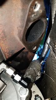
For making a 5-bolt downpipe that utilizes a V-Band flange, you will be using the 2.5" to 3" reducer that I listed in the parts list. You will cut both the 2.5" and 3" sides down to as short as possible (so the exhaust doesn't get too close to the body). The 2.5" side will be welded to the 5-bolt flange and a 3" V-band will be welded to the 3" end. There will be an ear on the transmission that you will have to grind down or else you won't be able to fit the exhaust onto there. If you look close at the provided picture, you can see some leftover shavings where it was grinded down. I don't have a close up pic when I had it done but it should look something like this.

 By utilizing V-bands, it allows some rotation in the exhaust for clearance. This picture is before I had the flex bellow welded onto the downpipe.
Here it is with the flex bellow:


This manifold places the wastegate in a terrible place. You need to make a custom relocation pipe. You will utilize 1.5" piping. For your wastegate reference, do not get it from the intake manifold! The wastegate diaphragm isn't supposed to see vacuum. If your turbo compressor housing has the fitting on it, use it. If it doesn't, get a bung welded onto your intercooler piping and reference it off of that.


The last picture is when the pipe fell off in the middle of the street. Heat cycling had loosened the bolts holding the pipe to the manifold.
Behind the intake manifold, there are three nipples which usually have torn caps on them. You will utilize two of these. One will have a line for your BOV reference and the other will have a line for your boost gauge running into the cabin. Replace the cap on the unused one with a BMW piece. Use hose clamps to secure those in place. You can remove the valve that is clipped on near the nipples that was used for the SAP.


After you have removed your stock exhaust manifolds, you will have to use the double nut method to remove any left over studs and install your N54 studs. The eBay/Amazon cast manifolds need to have the face grinded down; it does not sit flat and will be an enormous exhaust leak. The picture represents how it is NOT supposed to be. Notice the gap near the top; it needs to sit completely flat.


At the moment, I have my intercooler piping going under the subframe for the hot side. I haven't had many issues but that is because I slow down for any bump and/or dip. Recently I hit a dip too quick and broke a clamp and dented my pipe. Check "Future upgrades" to see how I made it mostly over the subframe.


Venting your crankcase is VERY important! An improperly vented crankcase will blow out all your seals. In order to eliminate the factory CCV, all you really have to do is tap and plug off where the stock distribution piece goes and let your breather open. I initially did have a catch can but I had JB welded the fittings onto my valve cover which broke off eventually so it just breathes into the engine bay. There is nothing wrong with that setup; oil vapor just leaves a oily film on everything.


To fit the intake boot comfortably in its position, you must "reposition" the purge valve line like the video shows.
Here is what my engine bay looks like:


Everything typed below will be geared toward if the engine was pulled out.
With the engine out, it is a perfect time to regasket your entire intake system. Remove the intake manifold and change out everything underneath except for the CCV system.
The first modification you will be doing is for the fuel tank purge valve. The piece that clips on the bottom will be left alone but the hose on the rear end going into the intake manifold will be plugged up on the intake manifold side and you will let the end on the purge valve breathe out into free air.


Moving onto the throttle body; there are two locating tabs intended to align the stock intake boot. Those two tabs do not allow you to slide on the silicone coupler all the way on so you have to grind them down.

For making a 5-bolt downpipe that utilizes a V-Band flange, you will be using the 2.5" to 3" reducer that I listed in the parts list. You will cut both the 2.5" and 3" sides down to as short as possible (so the exhaust doesn't get too close to the body). The 2.5" side will be welded to the 5-bolt flange and a 3" V-band will be welded to the 3" end. There will be an ear on the transmission that you will have to grind down or else you won't be able to fit the exhaust onto there. If you look close at the provided picture, you can see some leftover shavings where it was grinded down. I don't have a close up pic when I had it done but it should look something like this.


Here it is with the flex bellow:


This manifold places the wastegate in a terrible place. You need to make a custom relocation pipe. You will utilize 1.5" piping. For your wastegate reference, do not get it from the intake manifold! The wastegate diaphragm isn't supposed to see vacuum. If your turbo compressor housing has the fitting on it, use it. If it doesn't, get a bung welded onto your intercooler piping and reference it off of that.


The last picture is when the pipe fell off in the middle of the street. Heat cycling had loosened the bolts holding the pipe to the manifold.
Behind the intake manifold, there are three nipples which usually have torn caps on them. You will utilize two of these. One will have a line for your BOV reference and the other will have a line for your boost gauge running into the cabin. Replace the cap on the unused one with a BMW piece. Use hose clamps to secure those in place. You can remove the valve that is clipped on near the nipples that was used for the SAP.


After you have removed your stock exhaust manifolds, you will have to use the double nut method to remove any left over studs and install your N54 studs. The eBay/Amazon cast manifolds need to have the face grinded down; it does not sit flat and will be an enormous exhaust leak. The picture represents how it is NOT supposed to be. Notice the gap near the top; it needs to sit completely flat.

When you are going to install the turbo to the manifold, use red Resbond on the studs that are to be installed into the manifold and blue Resbond on the nuts that will be securing the turbo to the manifold. Do not forget to tighten these because it is VERY difficult to access the nuts once the engine is back in the car.
You will need to hammer right under the passenger footwell in order to get clearance for your downpipe. If your exhaust touches the body anywhere, it transmits the vibrations throughout the entire car and it is very unpleasant.

Here is how your engine should look now except you should have your Turbo E46 motor mount arm installed and the SAP port blocked off. It replaces the stock passenger side motor mount arm.

One thing that worried me was how close the oil feed line got to the manifold so I wrapped it in exhaust wrap. I used a 90 degree adapter and hose clamped the feed line to my AC line to keep it away from the manifold.


At the moment, I have my intercooler piping going under the subframe for the hot side. I haven't had many issues but that is because I slow down for any bump and/or dip. Recently I hit a dip too quick and broke a clamp and dented my pipe. Check "Future upgrades" to see how I made it mostly over the subframe.


Venting your crankcase is VERY important! An improperly vented crankcase will blow out all your seals. In order to eliminate the factory CCV, all you really have to do is tap and plug off where the stock distribution piece goes and let your breather open. I initially did have a catch can but I had JB welded the fittings onto my valve cover which broke off eventually so it just breathes into the engine bay. There is nothing wrong with that setup; oil vapor just leaves a oily film on everything.

Mounting your intercooler all depends on the intercooler itself; some intercoolers have the mounts on the side and others at the top. If your car was an automatic at one point in its life and still has the auxiliary fan right behind the bumper, you will have to remove it and use the electric fan that cars with manual transmissions use which resides in the engine bay. I utilized the top two stock fan mounting points for my intercooler and cut off the bottom two so they wouldn't poke into the intercooler.

Silicone is NOT oil compatible! Turbo oil drain VERY important! When you go to tap your oil pan, make sure it is off the car and clean it out very good once you're done. It leaves a TON of shavings behind. Without proper drainage, your turbo will burn oil and you will leave a smoke screen behind. Try to go as big as possible. A majority of the internet seems to agree that -10AN is adequate for a drain however the inner diameter of -10AN is too small. I got stuck with the size I went because I drilled and tapped my pan which ended up cracking so I had to JB weld the fitting in there. I am using a 5/8" drain, draining to the stock oil drain bolt and have no issues. If your drain is done right, you won't face issues. Now, since I have experienced the headache with finding a perfect drain, I want you to do it right. They make flexible turbo oil drain tubes that can be custom fabbed to work for your application. It is commonly known as a "cummins turbo flex oil drain." What you would ideally do is have a compression fitting welded onto one end of the pipe and have the other end of the pipe welded to a flange that can bolt up to your turbo. The end with the nut would be welded onto the drain pipe and the other end would be welded to your oil pan.


IMPORTANT: VIEW "FUTURE UPGRADES" TO SEE AN UPDATE ON MY DRAIN
My oil drain looks like this


The hose I used for my drain is 5/8" and is from https://www.pegasusautoracing.com/productselection.asp?Product=3290
You know how your car has those two barbs on the stock intake boot? You couldn't find what people did when they turbo'd their car? Well I struggled with those same thoughts and came up with my own solution. I basically just welded a bung to my charge pipe with a barbed fitting to run some hose connecting the barb on my pipe to the barb on the stock fitting. This retains the vacuum supply to the brake booster and the pressure reference for your fuel pressure regulator.
If you are wondering about what injectors to use, I stick to do it once, do it right. I did 3 PSI on my stock injectors but had no idea what their duty cycle was at so I got Bosch 0280158123 627cc (Porsche 99760513202). I switched over to E85 so I will, once again, need bigger injectors so I don't run these at too high of a duty cycle. For the M54 intake manifold, you want extended nozzle injectors like the stock ones. Those determine where the fuel will be sprayed. If you get the ones with no tip, it'll just spray sloppily all over the intake manifold and would be inefficient. The injectors I currently have required no physical modifications to the fuel rail.
I went with a DW300 for an upgraded fuel pump but haven't thrown it in yet as the stock pump is still working. I had initially thrown in the pump but didn't use upgraded wiring so I just melted through the stock wiring. Here are some pictures for how you should wire it and where to get a convoluted PTFE fuel hose. https://www.autoperformanceengineering.com/html/kits.html I used the hose that's 8mm on end and 10mm on the other end. The part number for the E46 specific DW300 pump is 9-301-1031


To fit the intake boot comfortably in its position, you must "reposition" the purge valve line like the video shows.
Here is what my engine bay looks like:


